Driver for the HD44780 based 16x2 liquid crystal display. More...
Files | |
| file | hd44780_lcd.c |
| Driver for the HD44780 based 16x2 liquid crystal display. | |
| file | hd44780_lcd.h |
| Driver for the HD44780 based 16x2 liquid crystal display. | |
| file | main.c |
| Example main routine demonstrating the HD44780 based 16x2 liquid crystal display. | |
| file | pin_defines.h |
| Definitions for pin mapping (for hd44780_lcd) | |
| file | pin_defines.h |
| Definitions for pin mapping (for hd44780_lcd) | |
Detailed Description
Driver for the HD44780 based 16x2 liquid crystal display.
- See also
- The files can be downloaded from the repo at: https://github.com/Jason-Duffy/AVRly/tree/main/content/modules/displays/hd44780_lcd/example
README
Introduction
The Hitachi HD44780 LCD (Liquid Crystal Display) controller is an extremely popular IC (Integrated Circuit) in use since the 1980's. It can drive upto two lines of 8 characters each, and can be addressed using either an 8 bit of 4 bit parallel data bus, plus some control pins. This driver and example application was written from the datasheet, which can be found here.
This example is for a 16x2 LCD module, with the HD44780 LCD controller IC on board.
Interface
For this example, we will use the controller in 4 bit mode, it uses fewer precious GPIO's, but takes twice as long for each character or instruction to be written to the display. The pins and their uses are shown below, note that pins D0 - D3 can be left unconnected in 4 bit mode. As we are not using the display in read mode, we can just tie the RW pin to ground, freeing up a GPIO pin on the host MCU.
| Pin | Function |
|---|---|
| VSS | Ground Connection |
| VDD | +5V Connection |
| VO | Contrast Adjust |
| RS | Register Select |
| RW | Read/Write Select |
| E | Enable (Latch) |
| D0 | Data Pin 0 |
| D1 | Data Pin 1 |
| D2 | Data Pin 2 |
| D3 | Data Pin 3 |
| D4 | Data Pin 4 |
| D5 | Data Pin 5 |
| D6 | Data Pin 6 |
| D7 | Data Pin 7 |
| A/LED+ | Backlight+ (Annode) |
| K/LED- | Backlight- (Cathode) |
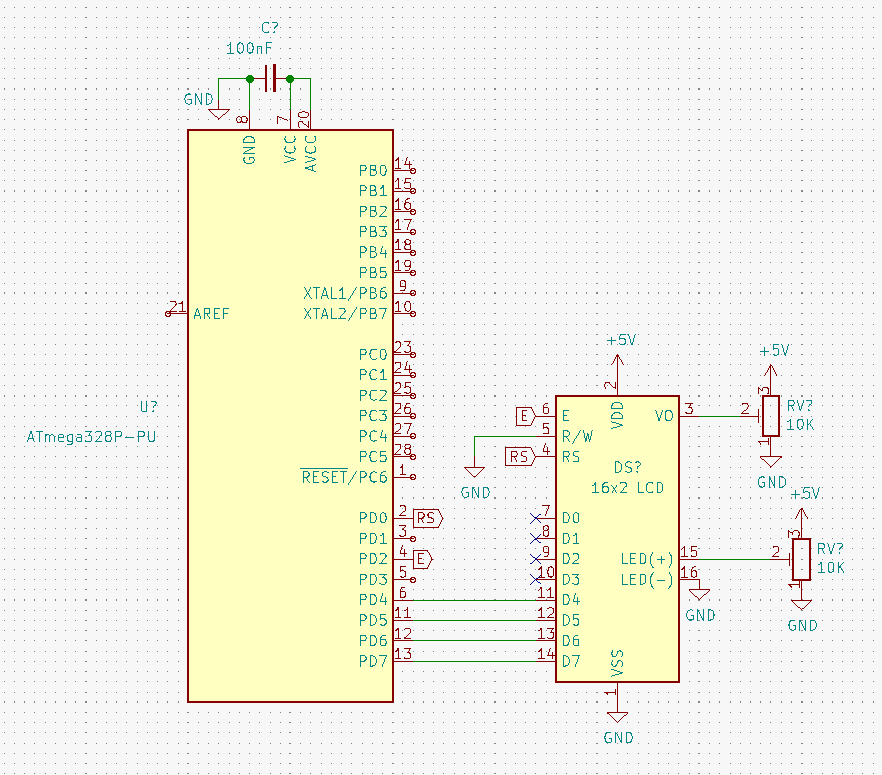
The connections are to be made as shown in the schematic below. Note the variable voltage control on pins VO and LED+; if you don't have trim pots to hand, you can just make 2 simple voltage dividers for the contrast and backlight adjustment using fixed value resistors.

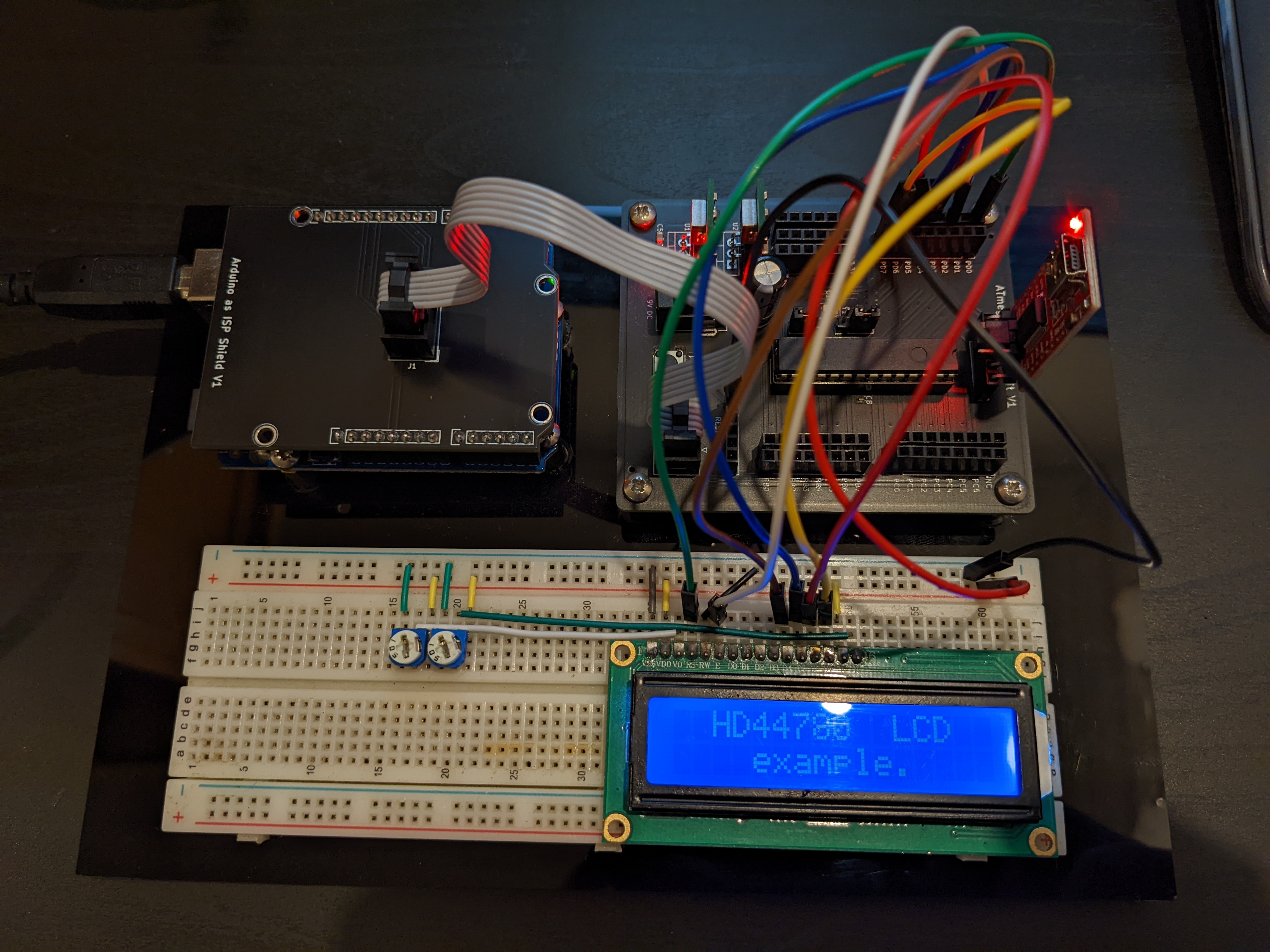
This can easily be built on a breadboard as shown below with the AVRly Dev Kit.

How it Works
The HD44780 is essentially just another microcontroller. When it's configured in 8 bit mode, an ASCII character is sent to our host MCU's GPIO port, such that all 8 bits of the ASCII character are output at the same time, or in parallel. The character "A" for instance is 01000001 in binary, or 65 in decimal, so our port will now look like this:
| Pin | Voltage Level | Logic Level |
|---|---|---|
| PD7 | 0V | 0 |
| PD6 | 5V | 1 |
| PD5 | 0V | 0 |
| PD4 | 0V | 0 |
| PD3 | 0V | 0 |
| PD2 | 0V | 0 |
| PD1 | 0V | 0 |
| PD0 | 5V | 1 |
The level of the RS (Register Select) pin determines whether we are writing an instruction (such as shift cursor to the left) or data (such as an ASCII character). So to send a character, we must first set RS high, then set up the data on the port, then we can pulse the E (enable) pin which acts as a latch, confirming the data on the port as valid. The enable pin is held low for a short time, then pulled high again, and the next character or instruction can be sent. There is however, a delay while the device computes and outputs the character or instruction, so a short delay is used to allow for this. There is the option to poll a busy flag to see when the instruction has been completed, but I found that it introduced fragility to the system so opted to leave it out.
In 4 bit mode, we have to send out the data 1 nibble (4 bits) at a time, starting with the most significant bits (MSB), and we also habe to pulse the enable pin after each nibble. This means it takes around twice as long for each character or instruction to be sent, but we are able to free up 4 GPIO pins which might come in handy later.
Example Application
In main.c (or whichever file you'd like to access this API) #include the header file for the HD44780 driver.
Next, we instantiate the config object and assign the desired configuration options. Note that if two line display is selected, then the font size MUST be 5x8.
After entering the main routine, the address of the lcd_config object is passed as a parameter into the init_lcd() function, and a copy is stored at file scope level in the driver.
Now the configuration and initialisation has been taken care of, we are free to use the rest of the functions in the API. If we want to change our configuration settings at any point, we can simply change the member variables of the config object, then call lcd_reconfigure(). The full, documented list of functions available in the API can be found in the file reference.
If you take a look at the example main routine, you'll notice the code to do this is quite long and cluttered. Usually we would seek to avoid such low-level detail in main.c, so if you use this driver in your project it's advisable to add another abstraction layer, such as "display.h" and "display.c". The config and initialisation can be moved into an init_display() function, and the details of printing to the screen can be wrapped in functions such as display_draw_welcome_screen() etc. This makes for a much tidier and easier to read main.c file, and provides better architectural boundaries in your projects.