Files | |
| file | atmega_i2c.c |
| I2C communications driver for AVR MCU's. | |
| file | atmega_i2c.h |
| I2C communications driver for AVR MCU's. | |
| file | pin_defines.h |
| Definitions for pin mapping. | |
Detailed Description
- See also
- The files can be downloaded from the repo at: https://github.com/Jason-Duffy/AVRly/tree/main/content/modules/avr-peripheral-features/comms_protocols/i2c/example
README
Introduction
I2C (Inter-Integrated Circuit), also known as I2C, IIC, or TWI (Two Wire Interface) is a Syncronous, packet-switched serial communications bus protocol designed for short distance intra-board communication. It's often favoured over SPI communication where there are many devices on the bus and not enough GPIO lines to have a CS line for each, as I2C uses a 7 bit address to select a device.
Interface
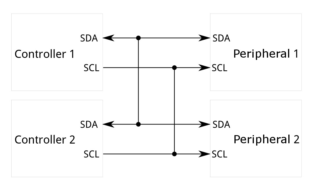
An I2C bus just requires 2 lines, SDA and SCL (plus ground of course), and these can be common to all devices.
SDA (Serial Data) is for the packets of data to be sent, and SCL is the clock line to synchronise all the devices on the bus.

To begin an I2C conversation, a start condition is required. The start condition consists of the SDA line being pulled from high to low while the SCL line is high. The strat condition serves to wake the receiving device on the bus.
The next part of the data transmission is the address of the receiving device, in 7 bit format. Often an I2C device has jumper pads on it's module board, which can be bridged with solder to modify the address of the device, to avoid clashes with others.
Next comes the read/write bit, this bit reads 0 for a write instruction and 1 for a read instruction.
Once a device has accepted that the address is a match, and recived the read/write bit, it will send an ACK (acknowledgement) bit as feedback to let the host MCU know to proceed with the rest of the message. The receiving device achieved this by holding the SDA line low during a high SCL period, while a NACK (no acknowledgement) is sent by passively leaving the SDA line pulled high during a high SCL period.
Next come the data bits, usually a byte followed by either a repeated start condition if another byte is to be sent, or a stop condition if the message is finished. The data bits are sent MSB first, and an ACK is expected after each byte.
The stop condition is performed by pulling the SDA line from low to high while the SCL line is high. After this condition, you will need to send the start condition, address and read/write bit again to begin a new transmission to the device.
