Files | |
| file | main.c |
| Example main routine demonstrating the USART driver. | |
| file | usart.c |
| Driver file providing core USART communication between the target MCU and your PC. This file was adapted from Elliot Williams' Github repo hexagon5un. (link in the see also section below). | |
| file | usart.h |
| Driver file providing core USART communication between the target MCU and your PC. This file was adapted from Elliot Williams' Github repo hexagon5un (link in the see also section below). NOTE: This driver does involve blocking waits, this may be improved on in a later version. | |
Detailed Description
- See also
- The files can be downloaded from the repo at: https://github.com/Jason-Duffy/AVRly/tree/main/content/modules/avr-peripheral-features/comms_protocols/usart/example
README
Introduction
USART is a form of serial communication protocol, and stands for Universal Synchronous/Asynchronous Receiver/Transmitter)Transmitter. This protocal provides the option of synchronous or asynchronous modes (meaning with or without a clock signal line).
You may also see the term UART around (Universal Asynchronous Receiver/Transmitter) which refers to a system which only has the option of an agreed baud rate. The system featured in AVR microcontrollers is USART, however we will be using it in it's asynchronous mode here.
Interface
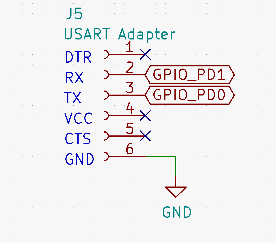
In this example, we will be using a USB to serial converter to communicate between a PC and the AVR MCU. The connections should be made as shown in the schematic below. Note that the RX and TX (Receive and Transmit) pins are crossed over - RX on the host MCU is connected to TX on the adapter and vice versa.

If you are using the AVRly dev kit, then the side of the adapter PCB the components are mounted on should be facing towards the MCU.
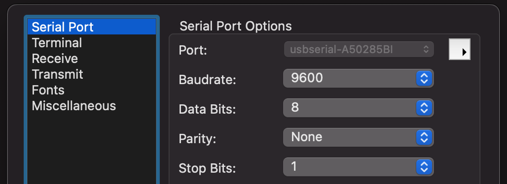
Connect the adapter to the PC using a USB cable, open up CoolTerm, go to Options > Serial Port Options > Port and select the one beginning with "usbserial". Set the baud rate to 9600, then press OK.

Press the Connect button, and the new connection status should be displayed on the bottom left of the screen. If it's connected, you're ready to start communication! If not, check your connections and repeat the steps above.
Data Transmission
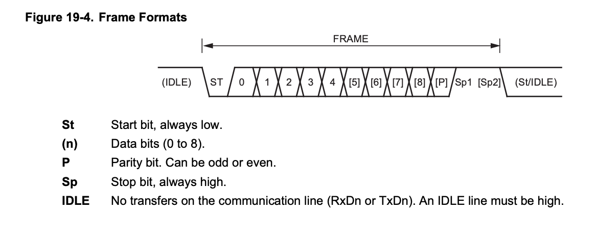
In USART communication, data is sent in "frames" with a start and stop bit, and optional parity check bits. The start bit (active low) signals to the receiver that a new data frame is being sent, then the data bits are sent (8 in this case), then parity check bits (not used in this case) and a stop bit (active high).

API Reference
On entry to the main routine of the application, we'll call the initialisation function for the USART driver, init_usart() - this function configures the hardware for use. It also requires the symbols BAUD and F_CPU to be defined, which is done in the Makefile.
From then on, we can call any function declared in the usart.h header file - the documentation can be found here.
Example Application
Once you have the MCU and adapter connected up and the CoolTerm settings configured, you're ready to flash the example application to the chip. Ensure the Makefile is configured properly for your development environment, and flash the chip.
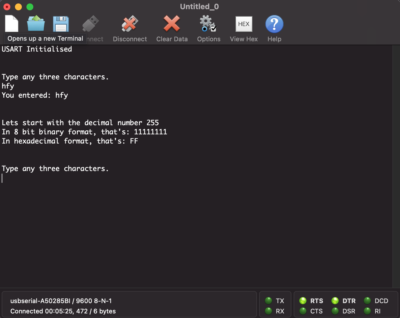
Once it reboots, you should start receiving messages on CoolTerm. Follow the prompts, and you should have a screen looking something like this.

Usage
USART communication has many uses in embedded systems, but I use it the most for logging output to aid in debugging my firmware. See the Log System Module for more.
It's worth noting that these data packets take a considerable amount of time to send, and also use blocking waits, so be careful where you use them!